Hardware FFT
In this tutorial, we demonstrate how to leverage AirStack BitStream to instantiate a hardware-accelerated Fast Fourier Transform (FFT) block in the AIR-T's FPGA. You will learn how to use the base Vivado project to insert a Xilinx LogiCORE IP FFT block into the RF sample datapath. We also provide the corresponding host-side Python software required to configure the radio, stream RF samples through the FPGA, and plot the resulting hardware-calculated FFT using the SoapySDR API.
AirStack BitStream by default provides a base Vivado project (.xpr) containing the Deepwave IP, an AXI4-Lite register space, and a pass-through datapath for radio samples. Additionally, the project can be configured to build specific tutorial designs like this one.
1. BitStream Vivado Project
For this tutorial, the AirStack BitStream Vivado project comes with a configured Xilinx FFT IP core and top level SystemVerilog for the datapath.
To enable the FFT build configuration: Right click on the top_deepwave_fft.sv design file in the sources window. Then click Set as Top.
The Xilinx FFT IP
The xfft_0 IP source in the Vivado project is what is instantiated in top_deepwave_fft.sv.
The block is configured as follows:
- Number of Channels: 1
- Transform Length: 1024
- Target Clock Frequency: 125 MHz
- Target Data Throughput: 125 MSPS
- Architecture Choice: Pipelined, Streaming I/O
- Data Format: Fixed point, matching the 16-bit IQ sample format of the AIR-T ADCs.
- Input Data Width: 16
- Phase Factor Width: 16
- Scaling Options: Scaled
- Rounding Modes: Convergent Rounding
- ARESETn (active low): Enabled
- Output Ordering: Natural Order
- Throttle Scheme: Non Real Time
FPGA Design (SystemVerilog)
The top-level file top_deepwave_fft.sv contains all of the SystemVerilog source code for this tutorial. It is a modified version of the default top_deepwave.sv design.
Clock and Reset
The sample-processing datapath operates on the dwd_axis_clk domain. The active-low reset for the FFT core, xfft_resetn, is asserted by combining the reset lines of RX Channel 0 and RX Channel 1. Tying both reset lines together ensures that the FFT block remains in reset until software activates both streams simultaneously.
Datapath
The FFT demo intercepts samples on the rx0_m_axis receive path and routes them to two places: 1) into the FFT block and 2) to the AIR-T CPU via a DMA channel. The output of the FFT is sent to another DMA channel also heading to the AIR-T CPU.
FROM RADIO ->                                                  -> TO CPU
                   +-----------+     +-------+     +-----+
rx0_m_axis ------> | Packetize |---->| Split |---->| FFT |------> rx0_s_axis
                   +-----------+     +-------+     +-----+
                                         |
rx1_m_axis (unused)                      +----------------------> rx1_s_axis
The second channel of radio samples rx1_m_axis is unused and its ready signal is tied high to avoid overflow.
The Xilinx FFT core expects the input stream to have tlast asserted matching the expected transform size. For that reason the packetizing process counts incoming dwd_rx0_m_axis samples using pkt_len_counter and drives rx0_pkt_m_axis_tlast high for the final, 1024th sample.
// Packetize incoming RF from radio to size of FFT
localparam NFFT = 1024;
logic[31:0] pkt_len_counter;
logic rx0_pkt_m_axis_tvalid;
logic [31:0] rx0_pkt_m_axis_tdata;
logic [3:0] rx0_pkt_m_axis_tkeep;
logic rx0_pkt_m_axis_tlast;
logic rx0_pkt_m_axis_tready;
always_ff @(posedge dwd_axis_clk) begin
  if(rx0_pkt_m_axis_tvalid & rx0_pkt_m_axis_tready)begin
    if(pkt_len_counter < NFFT)begin
      pkt_len_counter <= pkt_len_counter + 1;
    end
  end
  if(dwd_rx_axis_rst[0])begin
    pkt_len_counter <= 0;
  end
end
always_comb begin
  rx0_pkt_m_axis_tvalid = dwd_rx0_m_axis_tvalid;
  rx0_pkt_m_axis_tdata = dwd_rx0_m_axis_tdata;
  rx0_pkt_m_axis_tkeep = dwd_rx0_m_axis_tkeep;
  rx0_pkt_m_axis_tlast = dwd_rx0_m_axis_tlast;
  dwd_rx0_m_axis_tready = rx0_pkt_m_axis_tready;
  if(pkt_len_counter >= NFFT)begin
    rx0_pkt_m_axis_tvalid = 0;
  end
  if(pkt_len_counter == (NFFT-1))begin
    rx0_pkt_m_axis_tlast = 1;
  end
end
The logic is designed to process exactly one packet of 1024 samples upon stream startup. Once pkt_len_counter reaches NFFT, rx0_pkt_m_axis_tvalid is pulled low and remains inactive until a hardware channel reset.
After rx0_pkt_m_axis_tlast is asserted on the final input sample cycle, this stream is split, or "broadcast," into two copies. This is accomplished with a combinatorial, interlocked ready/valid handshake that requires both Channel 1 DMA dwd_rx1_s_axis and the FFT core xfft_s_axis to be ready simultaneously.
// Split packet into both the FFT unit and to second RX DMA channel
always_comb begin
  // Interlock valid and ready to split/broadcast the stream in two
  dwd_rx1_s_axis_tvalid = 0;
  dwd_rx1_s_axis_tdata = rx0_pkt_m_axis_tdata;
  dwd_rx1_s_axis_tkeep = rx0_pkt_m_axis_tkeep;
  dwd_rx1_s_axis_tlast = rx0_pkt_m_axis_tlast;
  xfft_s_axis_data_tvalid = 0;
  xfft_s_axis_data_tdata = rx0_pkt_m_axis_tdata;
  // no tkeep on fft core
  xfft_s_axis_data_tlast = rx0_pkt_m_axis_tlast;
  rx0_pkt_m_axis_tready = 0;
  if(dwd_rx1_s_axis_tready & xfft_s_axis_data_tready)begin
    rx0_pkt_m_axis_tready = 1;
    dwd_rx1_s_axis_tvalid = rx0_pkt_m_axis_tvalid;
    xfft_s_axis_data_tvalid = rx0_pkt_m_axis_tvalid;
  end
end
Because both channels rely on shared reset and ready signals, host software must use the SoapySDR Time API to trigger simultaneous reception across both channels. If both channels are not started at the same time then an immediate overflow from tready=0 is likely to occur.
2. Loading onto FPGA
Generate Bitstream in Vivado can be used to create a .bit file. Follow the instructions in the Loading AirStack BitStream files onto the AIR-T section of the Programming Guide for loading this file into the AIR-T FPGA's flash memory.
3. DMA Configuration
The small transfer of just 1024 samples needs some special configuration to work with the DMA drivers provided by AirStack Core. See the RX Software Buffer Size section of the Programming Guide for more information.
This demo requires a rx_buffer_size_pages of 32 pages or less:
# Unload and reload the required AirStack drivers
sudo rmmod airpci
sudo rmmod xdma
sudo modprobe xdma rx_buffer_size_pages=32
sudo modprobe airpci
Without this configuration more data is expected from the hardware, the original 1024-sample buffer is held indefinitely, and a TIMEOUT occurs.
4. Host-Side Software (Python)
With the custom bitstream loaded and running, the AIR-T will now receive frequency-domain data on the first channel and raw time-domain IQ samples on the second channel.
The Python script fft_test.py is provided alongside the Vivado project inside the tutorials/fft/ directory. The script configures radio parameters (frequency, sample rate, gain), initiates the streams, reads the DMA buffers, and produces plots.
Synchronized Channel Activation
Because the FPGA logic combines the reset and ready signals for the two receive channels, both streams must be started at exactly the same time. In Python, this is accomplished by scheduling the stream activation with SOAPY_SDR_HAS_TIME:
# Synchronize channel start time to 1 second from now
start_time_ns = int(time.time() * 1e9)
sdr.setHardwareTime(start_time_ns, "now")
rx_time_ns = start_time_ns + int(1e9)

# Activate Stream at scheduled time for both channels simultaneously
sdr.activateStream(rx_stream, flags=SOAPY_SDR_HAS_TIME, timeNs=rx_time_ns)
Without this simultaneous start, immediate OVERFLOW is likely, and depending on DMA buffer sizes may result in no data transferred and a TIMEOUT returned.
Normalization: Hardware vs. Software FFT Gain
Raw 16-bit signed integer IQ samples are normalized to floating-point values in the range [-1.0, 1.0] by dividing by 2^15 (32768.0).
Software FFT Scaling: A software FFT (np.fft.fft) introduces an implicit processing gain equal to the transform size, N = 1024, causing single-tone magnitudes to scale up by 20 * log10(N) = +60.21 dB.
Hardware FFT Scaling: The Xilinx FFT IP core is configured in Scaled Mode, applying a bit-shift right by 1 (divide by 2) at each of the butterfly stages to prevent fixed-point overflow. This applies an internal scale factor of 1/N (1/1024, or -60.21 dB) relative to DFTs such as np.fft.fft.
Normalization Alignment: To compare outputs directly on a dBFS scale, the software FFT is multiplied by 1/N (1/1024). This aligns the software model directly with the hardware core's scaled output baseline, with a 0 dB offset.
# Process CH0 (Hardware FFT) & CH1 (RF Samples)
hw_raw = rx_buff_list[0].astype(float) / (2.0 ** (rx_bits - 1))
hw_fft_complex = hw_raw[::2] + 1j * hw_raw[1::2]

rf_raw = rx_buff_list[1].astype(float) / (2.0 ** (rx_bits - 1))
rf_complex = rf_raw[::2] + 1j * rf_raw[1::2]

# Compute raw Software FFT on CH1 RF samples
sw_fft_raw = np.fft.fft(rf_complex)

# Normalize SW FFT by 1/N (1/1024) to match Xilinx HW FFT Scaled Mode
sw_scale_factor = 1.0 / N
sw_fft_norm = sw_fft_raw * sw_scale_factor

# HW FFT in Xilinx Scaled Mode applies 1/N internally across 10 stages
hw_scale_factor = 1.0
hw_fft_norm = hw_fft_complex * hw_scale_factor
To measure residual gain differences after normalization, the test also calculates an optimal scale factor using least squares.
Result Outputs
Example console output:
[INFO] Device master clock rate: 125.000 MHz (unchanged)
=== Receiver Configuration ===
Receive Channels      = (0, 1)
Sample Rate           = 125.00 MSPS
Buffer Length         = 1024
Internal LO Frequency = 1.400 GHz
AGC Enabled
[INFO] Starting radio stream initialization
[INFO] Radio stream initialization complete

=== FFT Scaling & Normalization Info ===
SW FFT Scaling Factor Applied : 9.7656e-04 (-60.21 dB) [1/N = 1/1024]
HW FFT Scaling Factor Applied : 1.0000e+00 (0.00 dB) [Scaled in FPGA IP core]

=== FFT Comparison Results ===
HW FFT is already aligned with SW FFT.
Residual Scale Ratio (HW / SW): 0.999994 (-0.000 dB)
Cosine Similarity (0 to 1)       : 1.000000
Normalized MSE (Scale-Corrected)  : 2.935605e-07
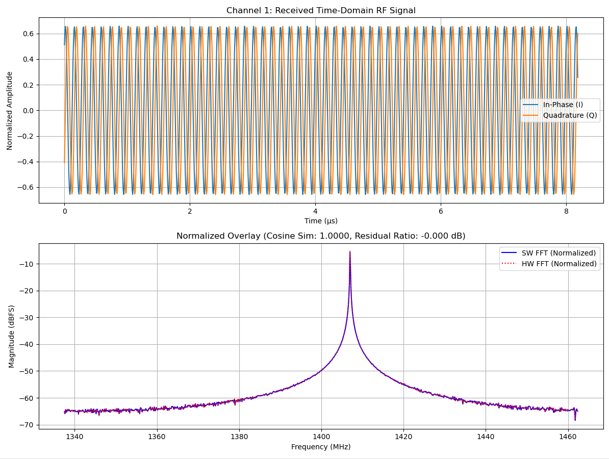
The visualization output is split into two panels:
- Plot 1 (Channel 1 Received Time-Domain RF Signal): Displays the raw in-phase (I) and quadrature (Q) time-domain waveforms captured over the 1024-sample window in microseconds (µs).
- Plot 2 (Normalized Overlay & Similarity Metrics): Provides a direct spectral overlay along with quantitative performance metrics, including Cosine Similarity (e.g., 1.0000) and residual scaling error in dB.
For example, when receiving a 1407 MHz tone from a signal generator: