AirStack BitStream
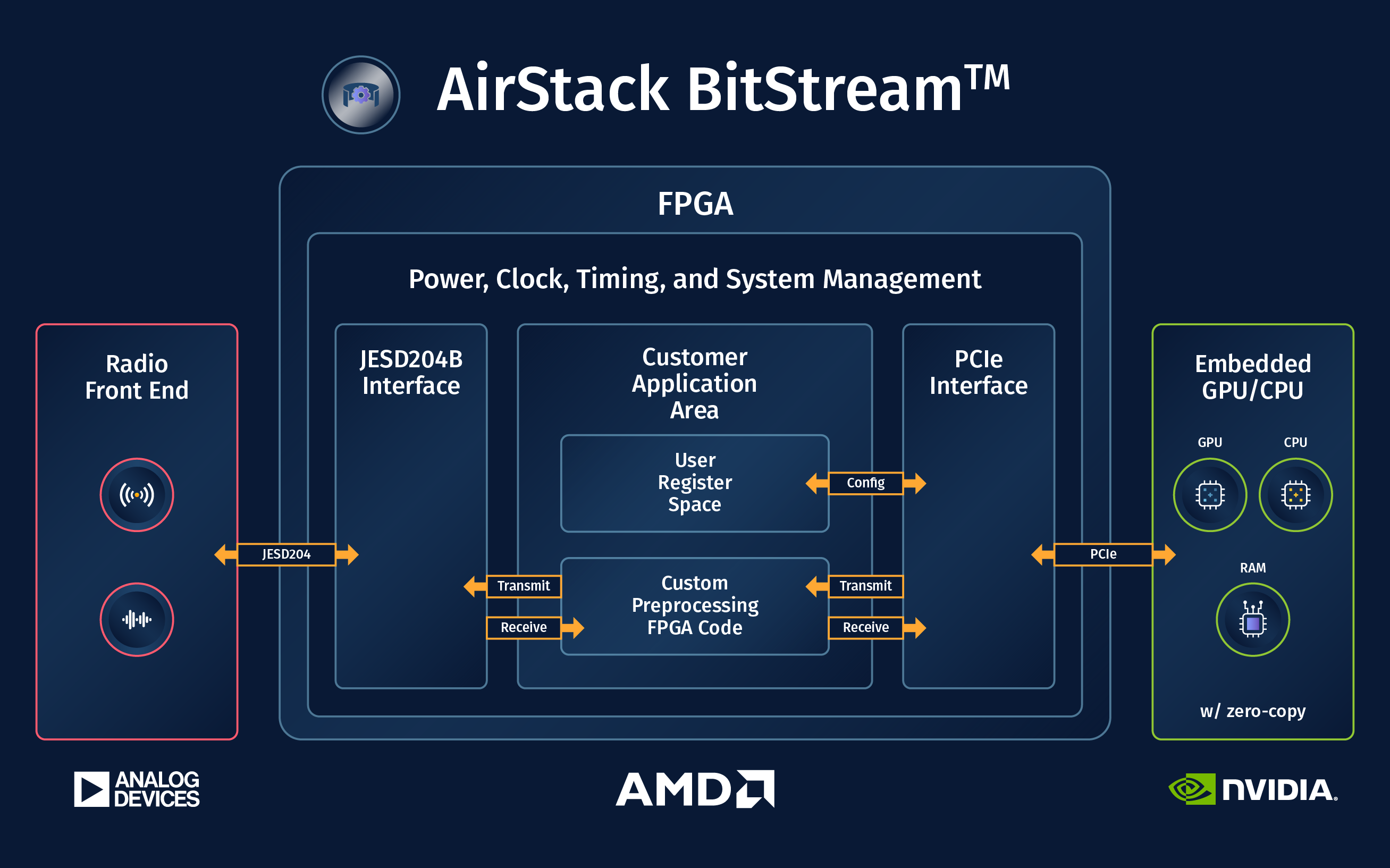
This document is an overview of AirStack BitStream, which is an environment where custom FPGA designs compatible with AirStack Core software can be created. More information can be found on the Deepwave documentation website.
AIR-T Model Compatibility
This documentation is written for the latest version of AirStack BitStream (v2.0.1+). More information is available in the release notes. For older versions of AirStack BitStream (v1.0 and earlier), please see this guide.
| AIR-T Model | Current AirStack BitStream Version |
|---|---|
| AIR7311 | 2.0.1 |
| AIR7310 | 2.0.1 |
| AIR8201 | 1.0 |
| AIR7201 | 1.0 |
| AIR7101 | 1.0 |
License
The license file is included with the download of AirStack BitStream and may be found on our docs page here.
Prerequisites
- An AIR-T with a compatible AirStack Core version installed:
Core 2.3.1+ for BitStream 2.0.1+Core 2.3.0 for BitStream 2.0.0- See release notes for differences between versions.
- A host machine with the following:
- AirStack BitStream downloaded from the Developer Portal.
- Xilinx Vivado 2023.2 installed.
- Xilinx JESD204 Core License.
- Confirm
jesd204license visibility in Vivado throughHelp > Manage License... - JESD204 evaluation licenses are compatible with AirStack BitStream. However, per Xilinx documentation: "the generated bitstream contains circuitry that disables the design after 2 to 8 hours of operation at the typical clock rate for the core. The actual duration of the operational period varies on a core-by-core basis. To start the device working again, you must reload the bitstream (reset or reprogram the device)."
- Confirm
AirStack BitStream Contents
- Deepwave IP files
- An example generated AXI4-Lite register space SystemVerilog module
- Top level SystemVerilog file, instantiates:
- the Deepwave IP core
- AXI4-Lite registers
- default pass through of samples back to the Deepwave IP core
- A test script for the AXI4-Lite register space
- A supplemental
.tclscript for Vivado requiring timing to be met by default - Vivado Project
.xprand supporting files for building.bitfiles - Copy of license agreement covering the files within AirStack BitStream
- Notes on upgrading from the previous AirStack BitStream version
- Copy of this programming guide
Getting Started
- Ensure the prerequisite requirements have been met.
-
In the directory where AirStack BitStream was downloaded extract the
AirStack_BitStream_<version>.tar.gzarchive:# For example on Linux systems: tar xvf AirStack_BitStream_vX.X.X.tar.gz -
Use Vivado to open the project
.xprfile inside of the newly createdAirStack_BitStream_<version>directory. -
In Vivado click the
Generate Bitstreambutton to confirm the full synthesis and implementation flow functions as expected. The resulting.bitfile is compatible with tests mentioned in below sections.
Upon successful .bit file creation Vivado will report many messages. Expected messages have been documented in spreadsheets exported by Vivado. See expected_vivado_messages.xlsx.
Signal Definitions
The names referenced here are from the top level SystemVerilog file included with AirStack BitStream.
Please refer to the AXI reference guide for more details.
Clock and Reset
dwd_axi_clk- 125MHz clock for the AXI4-Lite interface provided by the Deepwave IP core.dwd_axi_aresetn- AXI4-Lite interface reset, active low, synchronous.dwd_axis_clk- Samples 'master' clock for all AXI4-Stream interfaces provided by the Deepwave IP core. Configurable rate, see SoapySDR Master Clock below section.dwd_rx_axis_rst[*]- AXI4-Stream receive datapath resets, per channel, active high, synchronous.dwd_tx_axis_rst[*]- AXI4-Stream transmit datapath resets, per channel, active high, synchronous.
AXI4-Lite Interface
dwd_m_axil_*- AXI4-Lite bus for provided register space.dwd_axil_regs- An example generated AXI4-Lite register space module.
The example register space instantiates 32 four byte (32b) registers, offsets 0x00-0x7C.
The address space available on this AXI4-Lite bus is as follows:
64KB(17b addresses from0x00010000 - 0x0001FFFF).- Address decoding can be done using only the least significant 16 bits of address bus.
- See later sections on SoapyAIRT software interface for reading and writing these registers.
AXI4-Stream Interfaces
Serial 16b IQ samples pairs are in decoded from the 32b AXI4-Stream word as follows:
I = tdata[15:0];
Q = tdata[31:16];
All interfaces are in AXI4-Stream format with some limitations, as described below.
AXI4-Stream Limitations
tuserandtstrbsignals are not present nor supported.tkeepsignals are present but not supported by the software driver. It is required that all 32 bits of the 32btdatasignal are set and valid for each beat.- Optional
tdestandtidsignals are not present. These signals are used for multiplexing multiple logical streams over a single bus interface. Each of our AXI4-Stream interfaces represents a single logical stream, mapped one-to-one to a stream presented to software by the DMA controller.
Receive
dwd_rx*_m_axis_*- Stream of samples received from the radio. There is very little buffering behind this interface. Constant flow controltreadyis assumed, deassertingtreadydropstdatasamples.dwd_rx*_s_axis_*- Stream of samples for software DMA read. Flow controltreadyis asserted as DMA reads occur.
Note: RX s_axis_tready is not guaranteed to be continuously high as flow control is asserted per the AXIS specification. If the design requires a continuous burst that holds tready high for a certain number of cycles, inserting a an AXIS FIFO of that depth can achieve this.
Transmit
dwd_tx*_m_axis_*- Stream of samples from software DMA write. Streamtvalidis asserted as DMA writes occur.dwd_tx*_s_axis_*- Stream of samples to be transmitted by the radio. A constant stream of samples is expected during transmission. Whentvalidis deasserted and does not provide new samples for transmit, recent or zero value samples are transmitted untiltvalidis asserted again (or the radio is turned off).
Version Identificaton
The Deepwave IP core provides three four-bit values that can be used for versioning.
// Version bits
.ver_major(2),
.ver_minor(0),
.ver_patch(0),
These values are free to be used for any purpose and are printed by SoapySDRUtil --find as MAJOR.MINOR.PATCH semantic version number ex. carrier_firmware_version = BitStream 2.0.0.
Carrier Front Panel LEDs
The aux_led_green and aux_led_red signals correspond to the front panel AUX LED and are free to be used for any purpose. By default a slow green-red flash indicates a custom BitStream FPGA image was loaded.
IP Core Parameters
IP Core Allowed Values:
- Num Channels:
4or2 - RX/TX Buffer Sizes: Even power of two number of bytes (recommended minimum = 8k bytes)
As of AirStack BitStream 2.0.1 DMA buffer sizes are configurable per channel.
Warning: after changing IP core parameters, and before launching synthesis runs, right click on the deepwave_ip IP in the IP Sources tab and select Reset Output Products.... This will clean files autogenerated by Vivado and prevent missing file errors and other ways Vivado trips over itself.
Resource Usage
By default the BitStream design is configured to use the following resources:
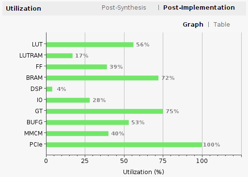
This includes integrated logic analyzer (ILA) instances for every AXI4 bus in the design as well as the default four channel large buffer size configuration of the Deepwave IP core. ILAs can be removed and the amount of resources used by the IP core can be reduced, see below sections.
Two Channel Mode
To make additional FPGA resources available, the Deepwave IP core can be configured into a two channel mode. Num Channels = 2 when configuring the IP from the catalog. This is recommended but not required for AIR-T 7310 users with only two RX and TX channels available anyway.
Buffer Size
To make additional FPGA BRAM resources available the size of DMA buffers inside the IP core can be reduced. Buffer Size parameters can be set for both for Rx and Tx directions.
By default sizes are large, near maximum in size and using most of the FPGA BRAM resources. This is to support continuous full rate receive and transmit - with an emphasis on transmit. By default transmit datapaths are given four times the buffer space than receive.
If configuring the IP core to have different buffer sizes it is best to evaluate receive overflow (dropping samples) and transmit underflow (gaps between samples) performance for your application. By default overflow and underflow events are reported by the SoapyAIRT API.
Loading AirStack BitStream files onto the AIR-T
-
On the AIR-T, load the
.bitfile into FPGA flash memory:airstack_firmware_update -f top_deepwave.bitNotes:
- The flash update utility will not recognize custom builds and will report that the contents of your .bit file are
UNKNOWN. This is OK. - Stock AirStack Core firmware images can be found installed in on the AIR-T.
- Ex.
/lib/firmware/AirStack_Firmware_vX.X.X-1.bit
- Ex.
- The flash update utility will not recognize custom builds and will report that the contents of your .bit file are
-
Shutdown, unplug the power supply to the AIR-T, and plug it back in. The FPGA will only read from the flash memory after a full power cycle.
-
Onced powered on the AIR-T will load the
.bitfile from flash and configure the FPGA. -
On the AIR-T run the following to verify the
.bitfile was loaded sucessfully:SoapySDRUtil --findwhich should return a found AIR-T device with
carrier_firmware_version = BitStream X.X.Xand correcthardwarematching your AIR-T product:carrier = Deepwave Digital AIR73xx carrier_firmware_version = BitStream X.X.X ... hardware = AIR73XX ... url = https://www.deepwave.ai vendor = Deepwave Digital, Inc.Note: Seeing
Corein the carrier firmware version, ex.carrier_firmware_version = Core X.X.Xmeans the default AirStack Core.bitfile is loaded and running (not BitStream).
If any problems are encountered please contact Deepwave support via the Developer Portal.
Testing the Initial .bit file
Radio Samples Datapath
The AirStack BitStream FPGA design comes configured for basic radio receive and transmit functionality.
The primary method of communicating to/from the RF hardware (including the FPGA) in AirStack Core is via the SoapyAIRT interface. However, SoapyAIRT assumes several things about the configuration of the FPGA. These assumptions are:
- All data passed to/from the FPGA are signed 16-bit integer complex values. Note that SoapyAIRT also supports complex 32-bit floating point samples, but performs an internal conversion. Users can interpret/cast buffers of different types to-from the complex 16-bit format as needed for data transfers.
-
Radio samples to/from the AD9371 are always transferred at a sample rate matching the master clock rate (default 125MHz, 125MSPS).
- The SoapyAIRT
setSampleRateAPI call only works if the sample rate matches the master clock rate. AirStack Core 2.0 added the ability to change the master clock rate usingsetMasterClockRate. See below sections. - To support samples rates that do not match the master clock rate additional user custom resampling modules can be added into FPGA datapaths.
- The SoapyAIRT
If your FPGA design meets the above assumptions, the SoapyAIRT interface is the simplest path forward.
Please see the below SoapyAIRT section and the following examples as a starting point for your application code:
For more complex interactions with the FPGA that break any of SoapyAIRT's assumptions, it is recommended to communicate with the DMA and transceiver device drivers directly. Please contact Deepwave support for code examples and further documentation.
Register Read + Write Test
The AirStack BitStream FPGA design comes configured with an AXI4-Lite register space.
A regrw_test.py test script is included that demonstrates reading and writing those FPGA registers using SoapyAIRT.
-
Run the test like so (no additonal arguments required):
python3 regrw_test.py -
The test attempts to read and write all of the allocated register space. For the subset of the address range currently in use write values are compared to read values to confirm registers are functioning correctly.
Testing allocated FPGA register address space...
...
Test passed.
Xilinx Virtual Cable
The Deepwave IP core along with the airpci_xvc_server program included with AirStack Core can be used to do remote cable-free Chipscope and other debug.
The Xilinx Virtual Cable protocol can be used as follows:
- On the AIR-T start the XVC server
sudo airpci_xvc_server
Which will print a message like:
INFO: To connect to this xvcServer instance, use url: TCP:airt:2542
-
On your host PC running Vivado use Hardware Manager to add a virtual cable hardware target. Use the hostname and port as printed from
airpci_xvc_server. -
To see the ILAs in your design right click on the debug bridge and configure the path to your debug probes
.ltxfile. Vivado produces this file in the same directory as the corresponding.bitfile.
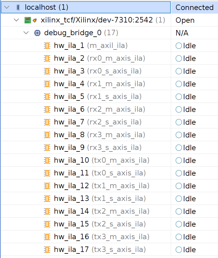
Debug ILAs
The AirStack BitStream FPGA design comes configured with Chipscope ILAs for the AXI-Lite Control and Status bus and all streaming data AXIS channels. See above Xilinx Virtual Cable section.
SoapyAIRT Functionality
Register Read and Write
As shown in regrw_test.py, SoapyAIRT provides an interface to read and write FPGA registers corresponding to the AXI4-Lite interface provided by the Deepwave IP core.
sdr.writeRegister('BitStream', addr, write_val)
read_val = sdr.readRegister('BitStream', addr)
The register range 'BitStream' includes the base offset of 0x10000. User addr values take the form of 16 bit addresses 0x0000 - 0xFFFF.
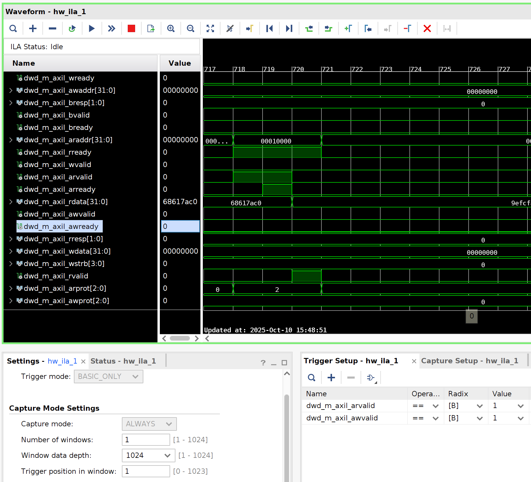
As captured by an ILA, the first random data write from the above test looks like so:
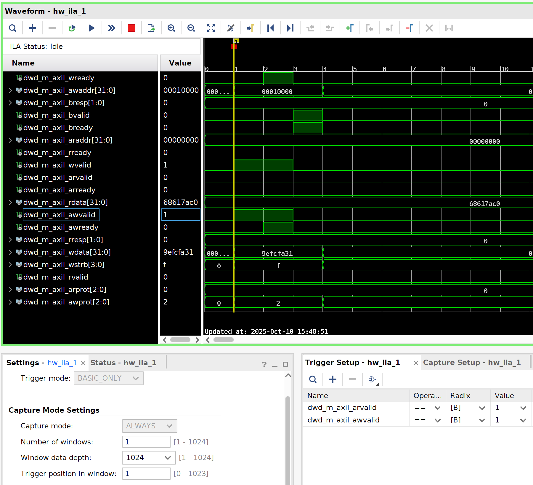
Later in the same capture it is followed by a read at the same address to confirm the register functionality.
Master Clock Rate
Setting the AIR-T's master clock rate changes the frequency of the dwd_axis_clk clock in the design.
Ex. Setting the master clock to 125MHz also sets sample rate to 125 MSPS for a receive channel using SoapyAIRT:
rx_chan = 0                               # RX1 = 0, RX2 = 1, etc
fs = 125.0e6                              # Radio sample rate
master_clock = fs                         # Sample rate will be the same as master clock
# BitStream designs cannot directly set the sample rate
# unless it matches the master clock rate
# sdr.setSampleRate(SOAPY_SDR_RX, rx_chan, fs)
sdr.setMasterClockRate(master_clock)      # Set the master clock
sdr.getSampleRate(SOAPY_SDR_RX, rx_chan)  # Can confirm the current sample rate
Setup and Activate Stream
The dwd_rx|tx_axis_rst[*] reset signals are asserted until the corresponding stream is activated.
sdr.activateStream(stream) # releases reset
This function of this reset is to prepare the DMA channel for upcoming data transfers (potentially bounded by AXIS tlast markers). Without this reset the design can end up with stale old/extra/missing bytes in the stream. It is important to have this reset connected to ensure continuous/uninterrupted/aligned data in the DMA channel from activateStream on forward in time.
Read Stream
When software attempts to read samples (32 bits|4 bytes per complex sample) from the stream, ex. a line like:
sr = sdr.readStream(rx_stream, [rx_buff], N, timeoutUs=timeout_us)
This attempts to transfer enough bytes to fill the buffer with a continuous stream of dwd_rx*_s_axis data from hardware. How many bytes are received depends on how much data the FPGA has provided and if/when it has marked off its AXIS tlast cycles.
-
If the FPGA has signaled
tlastbefore transfering the expected number of bytes, there will be a SoapySDR exception about not receiving all the data requested and timing out. -
If the FPGA has signaled
tlastat exactly equal to the requested rx buffer size, then readStream should return normally. -
If the FPGA has not yet signalled
tlastbefore transfering the expected number of bytes, then readStream will only return the first N samples requested. The next readStream calls will receive the remaining bytes.
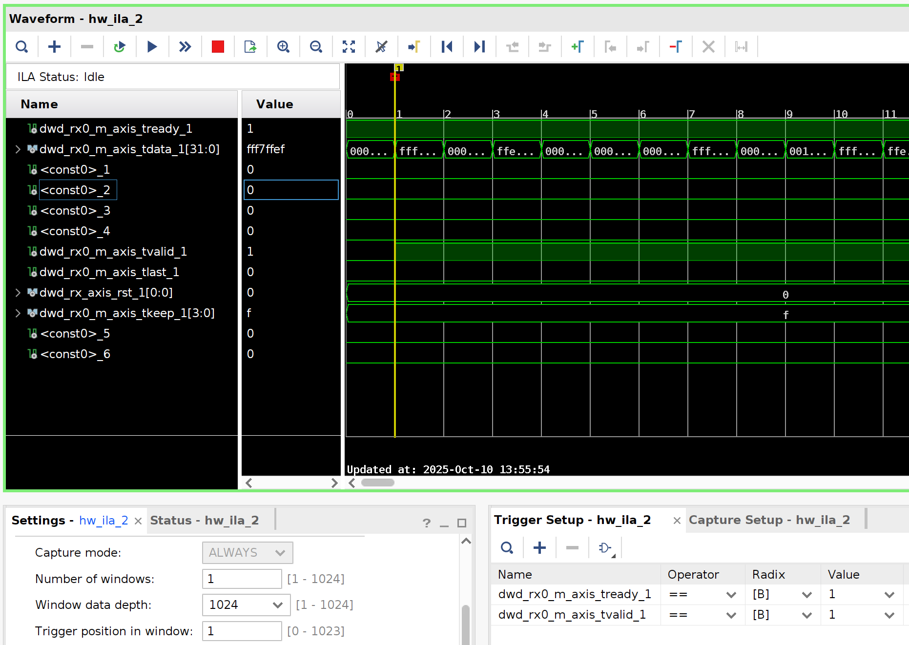
Data is transfered as both tvalid and tready are asserted, for example:
Write Stream
When software attempts to write samples (32 bits|4 bytes per complex sample) into the stream, ex. a line like:
sr = sdr.writeStream(tx_stream, [tx_buff], N, timeoutUs=timeout_us)
This attempts to transfer the contents of the buffer continously into the hardware via dwd_tx*_m_axis. How many bytes are transmitted depends on how much data the FPGA accepts before timeout.
As of AirStack BitStream 2.0.1 only writeStream() calls that set the SOAPY_SDR_END_BURST flag will see an AXIS tlast cycle at the end of the data stream. See TX Streams section of the AirStack Core programming guide on continuous TX streams.
Data is transfered as both tvalid and tready are asserted, for example a write of 512 samples can look like:

Time API
The SoapySDR Time API can be used with AirStack BitStream as a mechanism to control when samples flow in both receive and transmit directions.